 |
TSC Ferrite International (Soft Ferrite Cores)
TSC Pyroferric (Iron Powder Cores)
TSC–bourgeois (Magnetic Laminations)
|
TSC Ferrite International (Soft Ferrite Cores)
TSC Pyroferric (Iron Powder Cores)
TSC–bourgeois (Magnetic Laminations)
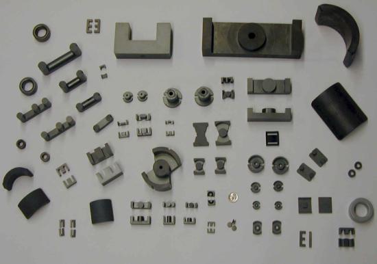
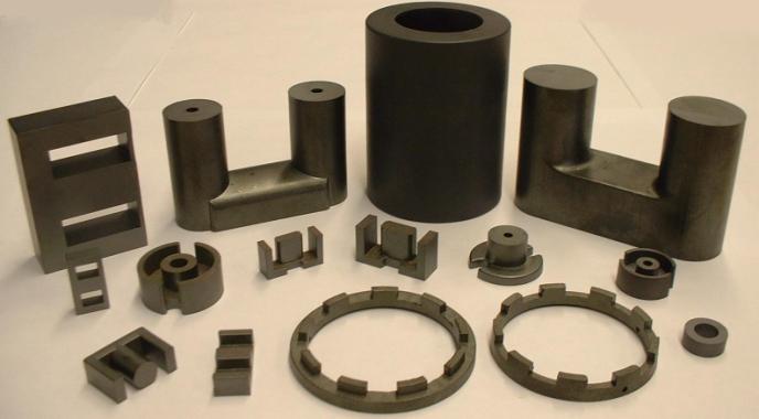
TSC International is a manufacturer of magnetic materials for all frequencies. Our many end markets include: automotive, computer, lighting, telecommunications, instrumentation, industrial and consumer product industries across the United States and around the world.
Our objective is to provide the highest value magnetic products to our customers through a combination of exceptional quality, delivery, service and price. We offer speed to market with one stop shopping for materials for all frequencies along with engineering support.
TSC FERRITE International was established in 1985 as a division of Tempel Steel Company and was purchased by Tempel Smith in 1990. TSC Ferrite International purchased the assets of AVX/TPC Thomson, Beaune France in 2004. TSC Ferrite International produces MnZn and NiZn soft ferrites, which are electromagnetic material used as cores for high frequency (10KHz-10MHz) transformers and inductors.
TSC Pyroferric, founded in 1935, is the oldest manufacturer of iron powder cores in the United States. TSC acquired them in 1995, and they continue to manufacture iron powder cores for power conversion, line filter and RF applications.
In 1992 TSC Ferrite International purchased the assets of TSC Arnold Technologies, which was formerly known as The Lamination Division of the Arnold Engineering Company. TSC Arnold Technologies fabricates magnetic laminations by stamping. The laminations are used to make low frequency (dc-10KHz) inductors and transformers.
A Joint Venture between TSC International and r.bourgeois known as TSC-bourgeois was formed in 1998 to provide Laminations to the North American Motor and Automotive Industries.
In 1999 TSC International acquired Accucore from Magnetics International. TSC Particle Core is a new revolutionary magnetic material that offers an alternative to Laminations.
Combined, TSC International has >125,000 square feet of manufacturing space and >70 presses dedicated to meeting our market’s demands.
POLICY STATEMENT
MISSION STATEMENT & QUALITY POLICY
It is the policy of TSC International to provide the highest value magnetic materials to its customers through a combination of exceptional quality, price, delivery and service.
OBJECTIVES
1. QUALITY: Achieve and maintain a quality system consistent with ISO-9000:2004 International Standards. Produce magnetic materials within that quality system which satisfy our customers for quality and consistency and which meet or exceed the industry standards such as those of the Magnetic Materials Producers Association.
2.
PRICE: Maintain cost control by encouraging
innovation, having a flat organizational structure with individual empowerment
at all levels and by expanding market share.
3.
DELIVERY: Achieve speed-to-market by maintaining
efficient administrative and productive systems, good internal communications
and fast factory throughput.
4. SERVICE: Maintain excellent service by creating working partnerships with open lines of communication at all levels.
5.
 |
INDEX
|
|
Product Line |
Page(s) |
|
About TSC International |
ALL |
Inside Cover |
|
Policy Statement |
ALL |
1 |
|
Index |
ALL |
2 & 3 |
|
Soft ferrite Manufacturing Overview |
Soft ferrite |
4 |
|
Definition of a soft ferrite |
Soft ferrite |
5 |
|
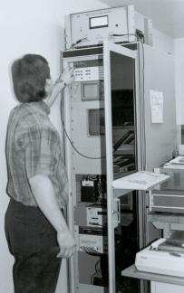
Test instrumentation |
Soft ferrite |
6 |
|
Ordering & Tolerances |
Soft ferrite |
7 |
|
Summary of soft ferrite material properties |
Soft ferrite |
8 & 9 |
|
TSF-50ALL (Flat Line) |
Soft ferrite |
10 |
|
TSF-5099 |
Soft ferrite |
11 |
|
TSF-7099 |
Soft ferrite |
12 |
|
TSF-7070 |
Soft ferrite |
13 |
|
TSF-8040 |
Soft ferrite |
14 |
|
TSF-5000 |
Soft ferrite |
15 |
|
TSF-Boost |
Soft ferrite |
16 & 17 |
|
TSF-010K |
Soft ferrite |
18 |
|
Soft ferrite Part Numbering System |
Soft ferrite |
19 |
|
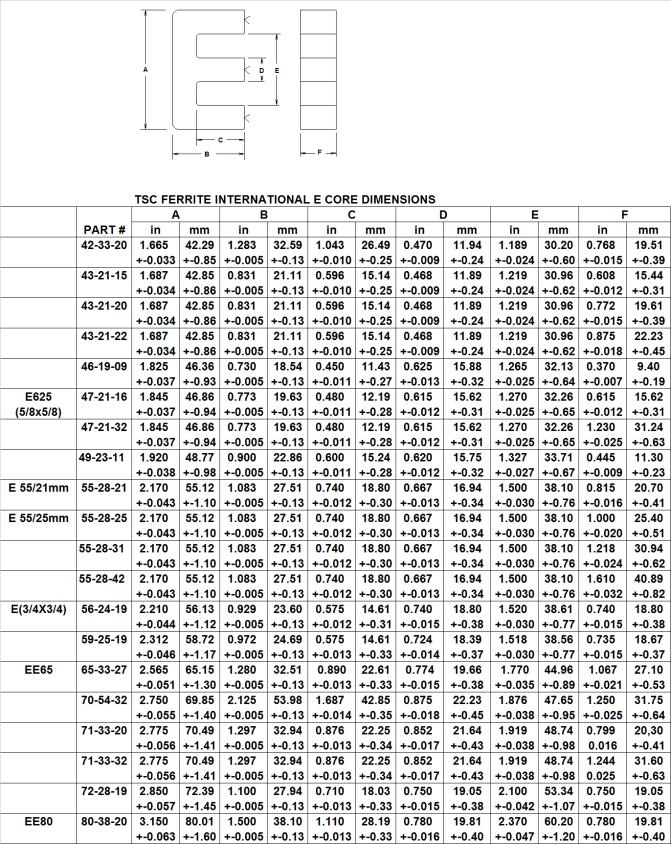
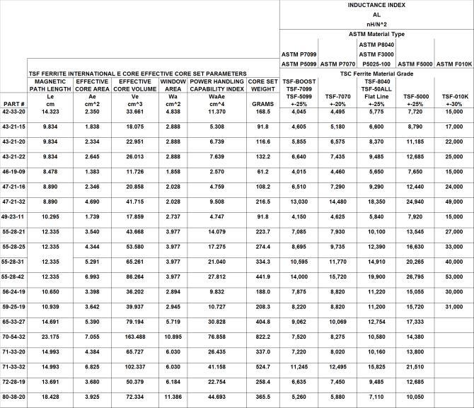
E cores |
Soft ferrite |
20 – 25 |
|
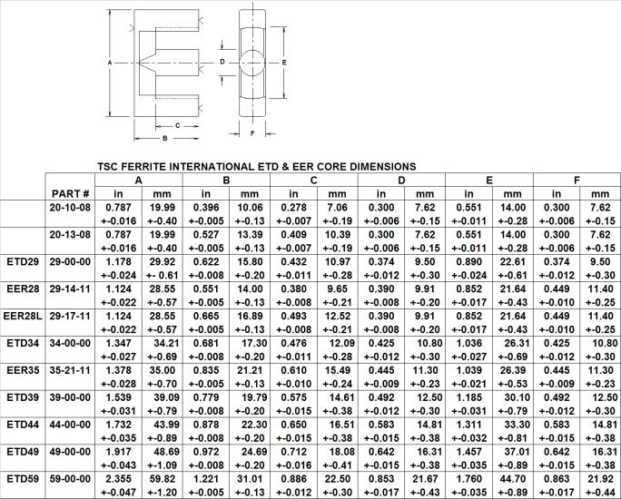
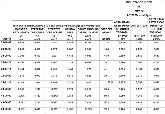
ETD Cores |
Soft ferrite |
26 & 27 |
|
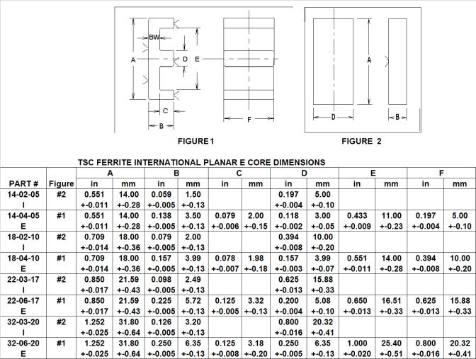
Planar E |
Soft ferrite |
28 |
|
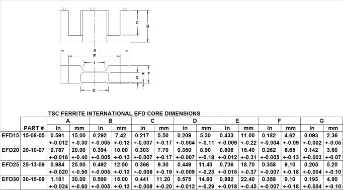
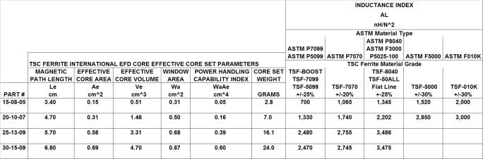
EFD Cores |
Soft ferrite |
29 |
|
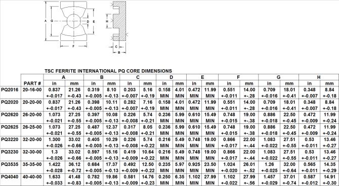
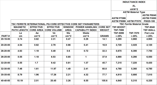
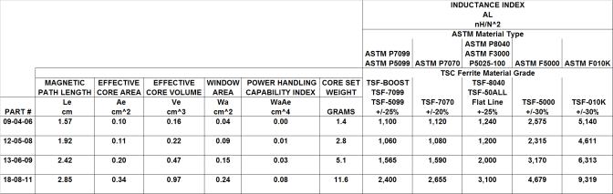
PQ Cores |
Soft ferrite |
30 |
|
EP Cores |
Soft ferrite |
31 |
|
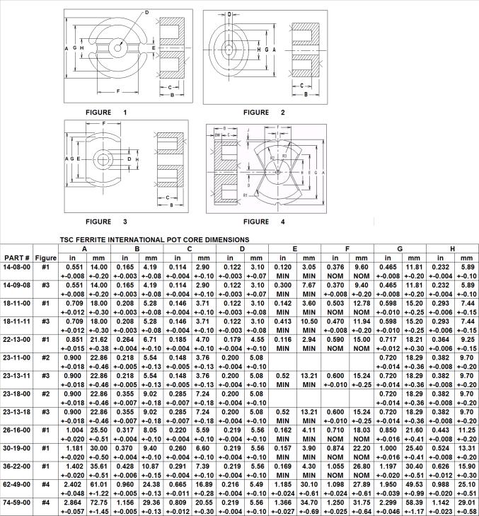
Pot Cores |
Soft ferrite |
32 & 33 |
|
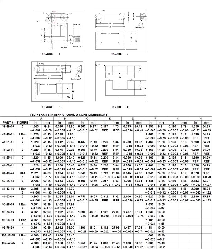
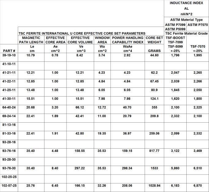
U Cores |
Soft ferrite |
34 & 35 |
|
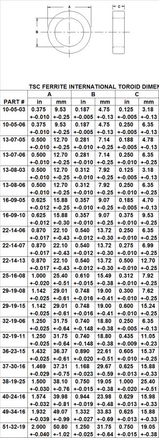
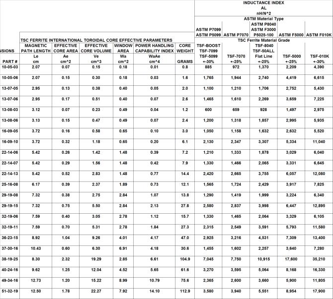
Toroids |
Soft ferrite |
36 & 37 |
|
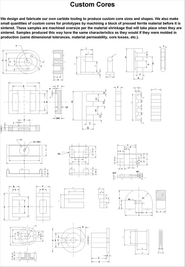
Custom cores |
Soft ferrite |
38 & 39 |
|
Composite E Cores |
Soft ferrite/Iron powder |
40 & 41 |
|
Composite Toroids |
Soft ferrite/Iron powder |
42 & 43 |
|
Iron Powder Manufacturing Overview |
Iron powder |
44 |
|
Iron Powder Part Numbering System |
Iron powder |
44 |
|
Iron Powder Finish & Tolerances |
Iron powder |
45 |
|
Iron Powder Material Properties |
Iron powder |
46 – 50 |
|
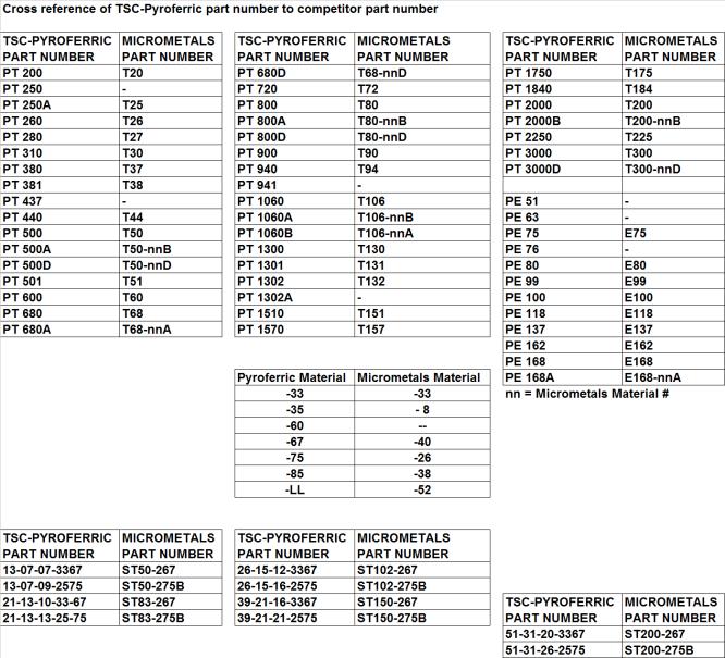
Iron Powder Material & Part Number Cross Reference |
Iron powder |
51 |
|
Iron Powder Toroids for Power Conversions & Line Filter Applications |
Iron powder |
52 – 55 |
INDEX (cont.)
|
|
Product Line |
Page(s) |
|
|||
|
Iron Powder E Cores |
Iron powder |
56 |
|||
|
Iron Powder Material Properties for RF Applications |
Iron powder |
57 |
|
|||
|
Iron Powder Toroids for RF Applications |
Iron powder |
58 & 59 |
|
|||
|
Iron Powder Rod Cores |
Iron powder |
60 & 61 |
|
|||
|
Iron Powder Thread Cores |
Iron powder |
62 – 66 |
|
|||
|
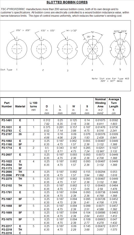
Iron Powder Bobbin Cores |
Iron powder |
67 – 69 |
|
|||
|
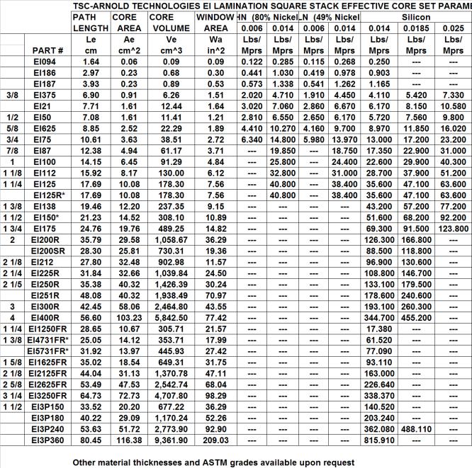
Lamination Material Properties |
Laminations |
70 – 73 |
|
|||
|
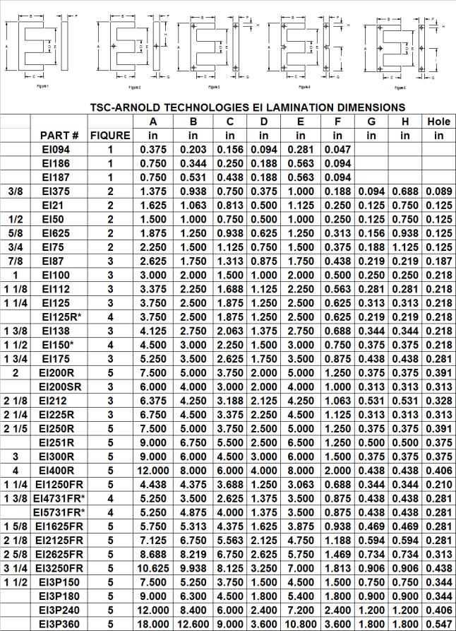
EI Laminations |
Laminations |
74 & 75 |
|
|||
|
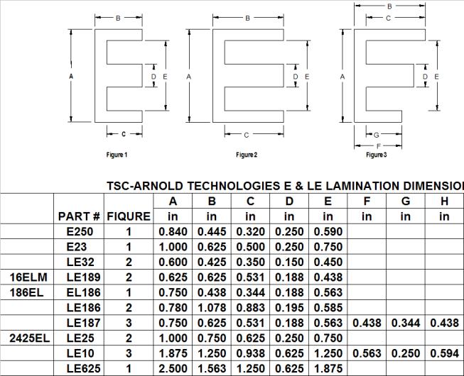
E and Long E Laminations |
Laminations |
76 |
|
|||
|
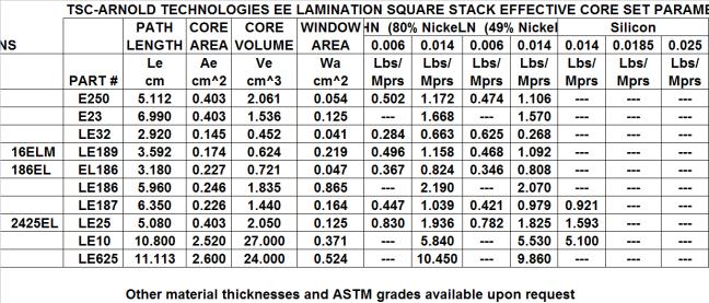
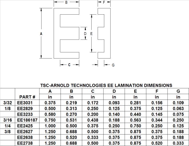
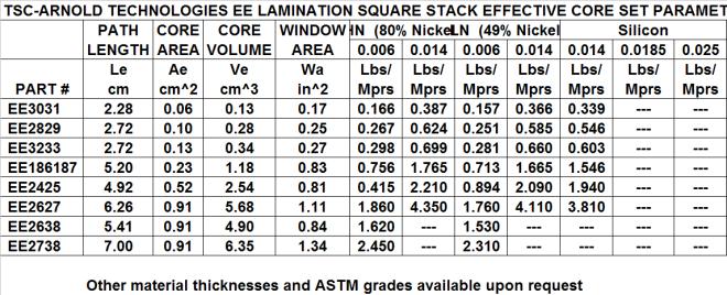
EE Laminations |
Laminations |
77 |
|
|||
|
Core size selection for power transformers |
ALL |
78 |
|
|||
|
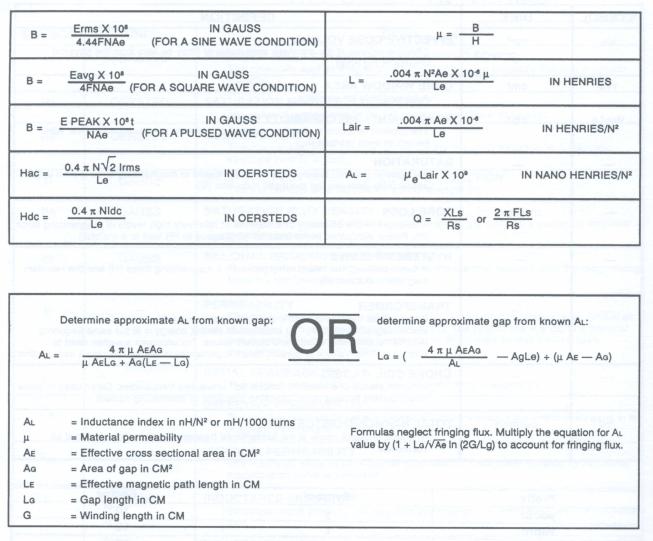
Formulas Used to Design Magnetics |
ALL |
79 |
|
|||
|
References |
ALL |
79 |
|
|||
|
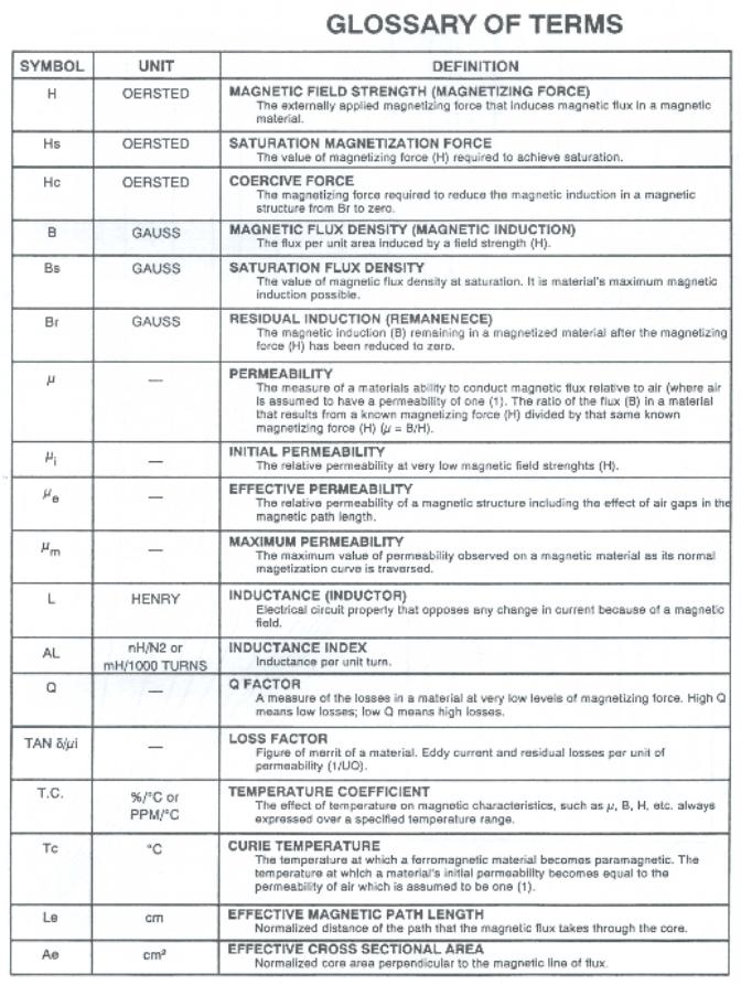
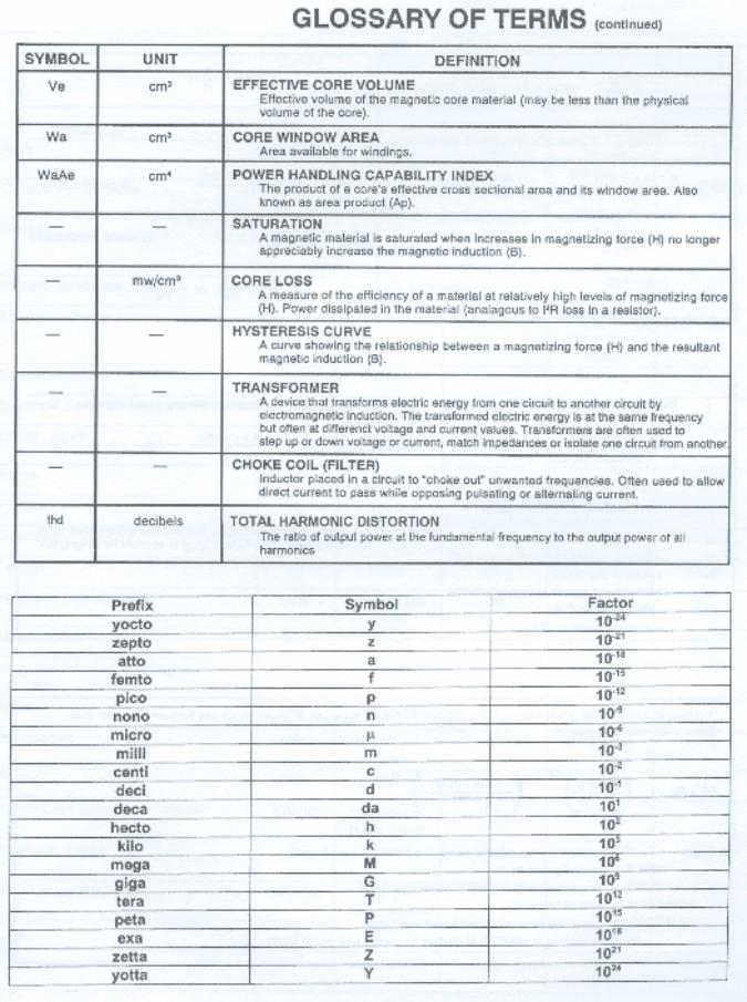
Glossary of Terms |
ALL |
80 & 81 |
|
|||
|
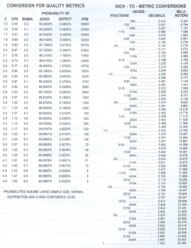
Customary to Metric Conversions |
ALL |
82 |
|
|||
|
Cross Reference of TSC International Parts |
ALL |
83 |
|
|||
|
Formulas for Quality Metrics |
ALL |
84 |
|
|||
|
Disclaimer & Warranties |
ALL |
84 |
|
|||
|
Quality & Dimensional Metrics Conversions |
ALL |
Inside Back Cover |
|
|||
 |
|
Test raw material (MnO, ZnO. Fe2O3) Inspect for purity ¯ Weigh & mix raw materials Control Composition ¯ Spray dry Obtain a powder form Control bulk density ¯ Calcine Powder (Pre-firing) Control magnetic saturation ¯ Wet mill Control particle size ¯ Spray dry to obtain a pressable powder Control bulk density ¯ Form (Compact powder into “green cores”) Control pressed density ¯ Sinter (fire “green cores” to obtain a ceramic with a spinel crystal lattice structure) Control grain growth ¯ Finish (grind, tumble, coat) Control gap and surface finish ¯ Audit to insure that all parts meet all the customers requirements ¯ Pack & Ship |
The process of manufacturing Soft Ferrites is made up of four basic steps: powder preparation, forming, sintering and finishing. At Ferrite International raw materials (manganese oxide, zinc oxide and iron oxide) are tested for purity levels. After the raw materials are approved they are weighed and wet mixed, and spray dried to a powder form then calcined. Calcining is pre-firing the material at a selected temperature between 800 degrees and 1100 degrees C thus creating a partial spinel structure and partially densifying the powder so that the pressed part will shrink less during the final sintering process. The calcined material is then wet milled to a specific particle size range. This particle size reduction enables better control of grain growth that occurs during the final sintering process. An organic binding agent is added to the slurry for the purpose of holding the pressed part intact. The slurry is then spray dried to provide a dry moldable powder composed of discreet spherical agglomerates with uniform characteristics.
The forming operation transforms the powder into a soft "clay like" material in the desired configuration. In this form they are called "green cores". The forming is done using presses and powder compaction tools. Because tool steels do not last under the wear of the abrasive Ferrite powder, carbide tools are used for large quantity items. The size, weight and thus the density of the green compact are all controlled within very tight tolerances.
To create the desired physical and magnetic characteristics the "green cores" are sintered in large kilns at temperatures between 1300 and 1450 degrees Centigrade. Close temperature and atmospheric control during sintering is critical. The sintering is divided into three stages. In the first stage the binders are driven off. The second stage is when the actual sintering takes place. The spinal crystal latus structure forms, the product shrinks and the magnetic characteristics are realized. The final stage is devoted to reoxidation and cool-down. Volume shrinkage is affected by the size, shape and the chemical composition. Each part must be molded oversize. A typical material may shrink 15% in any one linear dimension (approximately 50% of total volume).
Cores that will be assembled require machining. This process is critical to removing the final surface layer of reactive Ferrite (called skin) that result from sintering and to minimize any air gaps by insuring smooth flat and parallel surfaces. Some cores sets require gaps with tight tolerances in their flux path. This can be accomplished by grinding a pot core's center post or an E core's center leg. Because of the extremely hard, brittle and abrasive nature of the ceramic material diamond wheels and large amounts of liquid coolant are required for all machining operations.
Sintered toroidal cores are tumbled and sometimes coated with epoxy to eliminate any sharp corners or burrs that could damage wire insulation during the ensuing operation.
Finally the cores are tested electrically, inspected for dimensional and visual conformance and packed to be shipped to our customer.
|
Definition of a soft ferrite core
Soft Ferrites are ceramic electromagnetic material dark gray or black in appearance and very hard and brittle. The terms "SOFT" has nothing to do with their physical properties but refers to their magnetic characteristics. Soft magnetic materials also called electromagnetic exhibit magnetic properties only when they are subject to a magnetizing force such as the magnetic field created when current is passed through wire surrounding a soft magnetic core. This differs from hard magnetic (Permanent Magnets) in that once a hard magnetic material is magnetized by exposure to a magnetizing force it exhibits magnetic properties permanently.
A Soft Ferrite's magnetic properties arise from interactions between metallic ions occupying particular positions relative to the oxygen ions in its spinel crystalline structure. The magnetic domain theory suggests these interactions create magnetic domains, which are microscopic magnetized regions within the material. When no magnetizing force is present the magnetic domains are random and the net flux contribution is zero even though local domains are fully magnetized. When a magnetizing force is present the magnetic domains align in the direction of the magnetizing force resulting in a large net flux contribution.
Soft Ferrites are also semi-conductors meaning they are somewhere between conductors and insulators in their ability to conduct electron flow through the material.
Advantages Soft Ferrites have over other electro magnetic materials include their inherent high resistivity, which results in low eddy current losses over wide frequency ranges, high permeability and stability over wide temperature ranges. For inductor cores, transformer cores and other applications where electro magnetic materials are required to operate at high frequencies these advantages make Soft Ferrites paramount over all other magnetic materials.
Test Instrumentation & Methods
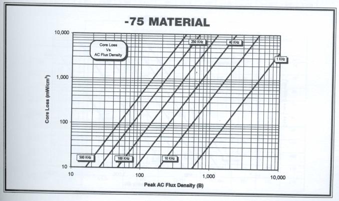
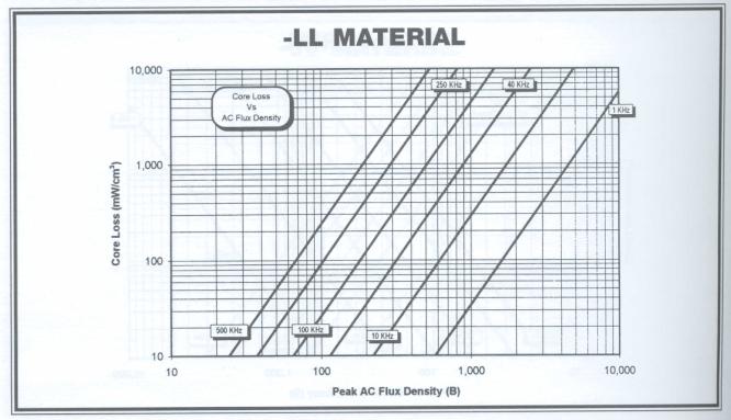
Core Loss
Published values of core loss have been measured on E21 size (41-16-12) double E cores. The cores are driven with an ENI Model 2100L RF Amplifier and measured using Clarke-Hess Model 2335 VAW meters under sine wave conditions. Flux densities were calculated using rms voltage values and effective core set parameters calculated per MMPA standard No. EUI310. Core loss density was calculated per the same standard. These curves are applicable to all sizes and configurations as long as the correct effective core set parameters are assumed. Data and graphical curves of core loss vs. temperature measured on ungapped core sets are included for each kiln firing and lot with each shipment of our products.
Initial Permeability
Published values of initial permeability have been calculated from measured inductance values at 5 gauss on toroids (OD=.870, ID=.540, HT=.250) using Wayne-Kerr model 6425 or model 3245 LCR meters. Flux density and permeability were both calculated using effective core set parameters (Le, Ae and Ve) calculated per MMPA Toroid Standard No. FTC410.
Power Permeability
(Permeability vs. Flux Density)
Published values of Power Permeability have been calculated from measured values of rms currents and voltages on 25-10-06 size double E cores using Clarke-Hess model 2335 VAW meters.
m = (L / Lair) = ((0.45*Erms)/(f*Irms*2.829))/((0.004*P*Ae*10-6)/Le)
Saturation Flux Density
Published values of saturation flux density have been calculated from integrated voltage measurements on 25-10-06 size double E cores induced by a specific magnetizing force (15 oersteds).
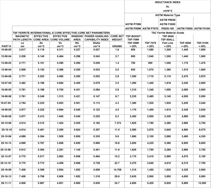
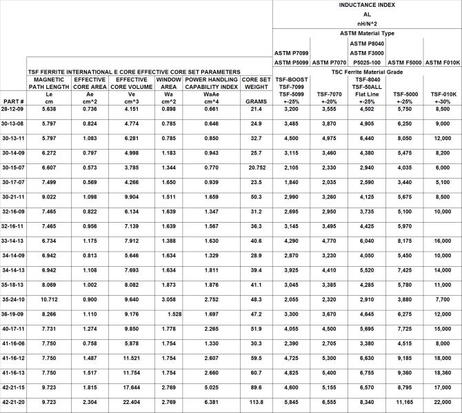
Inductance Index (AL Value)
Published Al Values were measured on Wayne-Kerr model 6425 or model 3245 LCR meters using 100 turn coils. Mated cores have a clamp pressure of approximately 5 pounds per square inch of mating surface. Statistical data including a histogram and capability indexes of the AL value on gapped and ungapped core sets are included with each shipment of our products.
Total Harmonic Distortion
We measure harmonic distortion on an Audio Precision
System Two (SYS-2022) in accordance to our customer’s part specific
specification. The test circuit primary series resistance, output load
resistance, frequency and drive level in Db, Vrms or Vpp are specified by our
customers.
Ordering Gapped Cores
Gapped Cores can be ordered 3 ways:
1. To a mechanical dimension.
2. Two gapped cores mated together to yield a specific AL value.
3. One gapped core mated with one ungapped core to yield a specific AL value.
When ordering cores to an AL value, it is important to specify whether 2 gapped cores are mated together or if 1 gapped core is mated with 1 ungapped core. It is also helpful if each customer supplies us with their coil to avoid differences in fringing flux that would result in a difference in AL measurements between the customer and the manufacturer. On our throughput grinder, we are capable of holding mechanical gap tolerances of +/- .0007". Because the relationship between AL and gap depth is a decaying exponential, the AL tolerance we are capable of is dependent upon the depth of the gap (larger gaps yield smaller AL values with tighter tolerances then do smaller gaps).
Tolerances
Problems periodically arise concerning magnetic and mechanical tolerances of ferrites. The nominal and spread of a sample lot is not always indicative of production lots. As an example, toroids are supplied to a nominal AL value based on material grade, and a tolerance of +-25%. The nominal AL value for a large number of production lots is considered to be at 0.0%, then the total spread of a large number of shipments will be +-25% around this nominal.
 |
|
Material Grade
|
Initial Permeability
|
Saturation Flux Density @15 oersteds |
Curie Temperature |
|
|
|
m0
|
Bs (Gauss) |
Tc (oC) |
|
|
TSF-50ALL “Flat Line” ASTM P5025-100 |
3,000 |
5,000 |
>230 |
Low loss & stable perm over wide temperature range |
|
TSF-5099 ASTM P5099 |
2,000 |
5,000 |
>210 |
Low core loss |
|
TSF-7099 ASTM P7099 |
2,000 |
5,000 |
>210 |
For high ambient temperature applications |
|
TSF-7070 ASTM P7070 |
2,200 |
5,000 |
>210 |
For potted applications |
|
TSF-8040 ASTM P8040 ASTMF3000 |
3,100 |
5,100 |
>210 |
All purpose material for integrated magnetics |
|
TSF-5000 ASTM F5000 |
5,000 |
4,300 |
>170 |
For filter inductors |
|
TSF-010K ASTM F010K |
10,000 |
4,300 |
>125 |
For low harmonic distortion |
|
TSF-Boost
|
2,000 |
5,000 |
>210 |
For dc bias applications |
|
TSF-0850 |
850 |
3,000 |
~140 |
NiZn for suppression of 30MHz to 200MHz signals |
|
TSF-0125 |
125 |
3600 |
~350 |
NiZn usable permeability up to 100MHz |
|
TSF-0040 |
40 |
2,600 |
~450 |
NiZn usable permeability up to 300MHz |
|
Soft Ferrite Material Constants |
|
|
Specific Heat |
0.25 cal / g / oC |
|
Thermal Conductivity |
10 x 10-3 cal / sec / cm / oC |
|
Coefficient of Linear Expansion |
8 to 10 x 10-6 / oC |
|
Tensile Strength |
7 X 10³ lbs / in2 |
|
Compressive Strength |
60 X 103 lbs / in2 |
|
Young’s Modules |
18 X 103 lbs / in2 |
|
Hardness (Knoop) |
650 |
|
Density |
4.8 g / cm3 |
 |
These meaningful grade names, like the meaningful dimensional portion of our part numbering system,
are meant to help our customers identify important characteristics of our parts by the part number alone.
TSF-50ALL
![]()
![]()
![]() Temperature
of low core loss (<room to >100°C)
Temperature
of low core loss (<room to >100°C)
![]() Core
loss at 100KHz, 1000 gauss (50 mw/cm3)
Core
loss at 100KHz, 1000 gauss (50 mw/cm3)
TSF-5099
![]()
![]()
![]() Temperature
of minimum core loss (100°C)
Temperature
of minimum core loss (100°C)
![]() Core
loss at 100KHz, 1000 gauss (50 mw/cm3)
Core
loss at 100KHz, 1000 gauss (50 mw/cm3)
TSF-7099
![]()
![]()
![]() Temperature
of minimum core loss (100°C)
Temperature
of minimum core loss (100°C)
![]() Core
loss at 100KHz, 1000 gauss (70 mw/cm3)
Core
loss at 100KHz, 1000 gauss (70 mw/cm3)
TSF-7070
![]()
![]()
![]() Temperature
of minimum core loss (70°C)
Temperature
of minimum core loss (70°C)
![]() Core
loss at 100KHz, 1000 gauss (70 mw/cm3)
Core
loss at 100KHz, 1000 gauss (70 mw/cm3)
TSF-8040
![]()
![]()
![]() Temperature
of minimum core loss (40°C)
Temperature
of minimum core loss (40°C)
![]() Core
loss at 100KHz, 1000 gauss (80 mw/cm3)
Core
loss at 100KHz, 1000 gauss (80 mw/cm3)
TSF-5000
![]()
![]() 5,000
permeability
5,000
permeability
TSF-010K
![]()
![]() 10,000
permeability
10,000
permeability
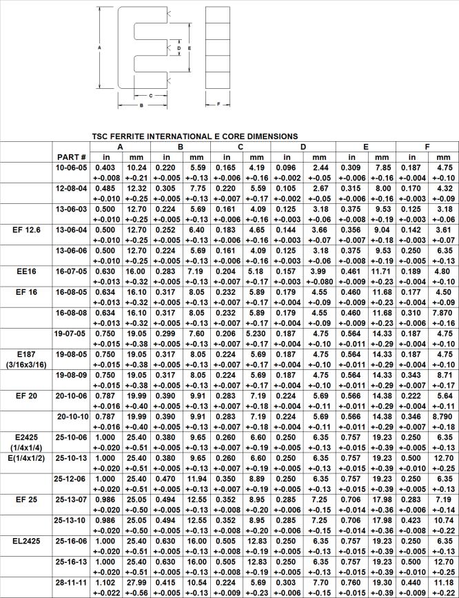
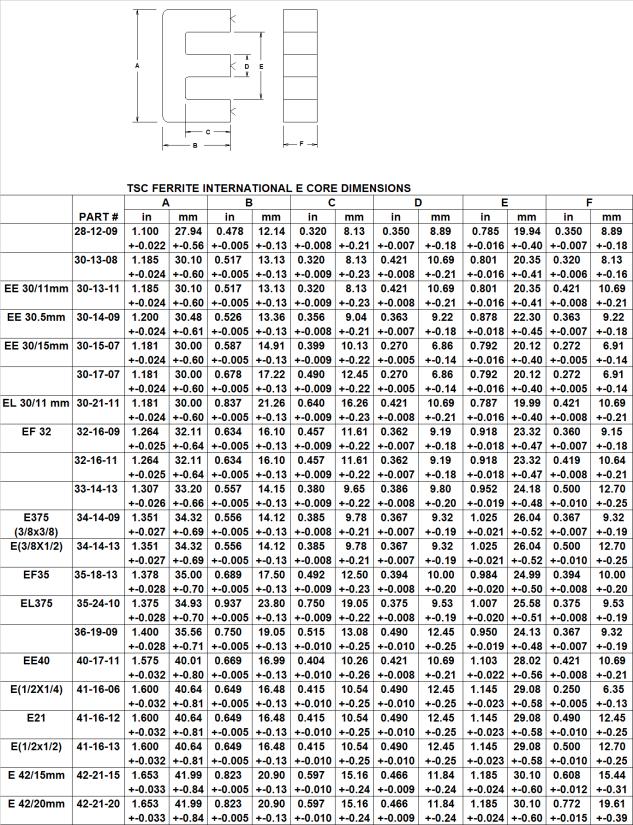
E CORES TSF-5099-25-10-06-0000
![]()
![]()
![]()
![]()
![]()
![]() Gap
code (-0000 for ungapped)
Gap
code (-0000 for ungapped)
![]() Nominal
thickness of core (F dimension) in rounded mm
Nominal
thickness of core (F dimension) in rounded mm
![]() Overall
leg length of one core (B dimension) in rounded mm
Overall
leg length of one core (B dimension) in rounded mm
![]() Back length (A dimension) in rounded mm
Back length (A dimension) in rounded mm
![]() Core material (TSF-5099)
Core material (TSF-5099)
![]() POT
CORES TSF-8040-14-08-00-0000
POT
CORES TSF-8040-14-08-00-0000
![]()
![]()
![]()
![]() Gap
code (-0000 for ungapped)
Gap
code (-0000 for ungapped)
![]() Nominal
pair height (2 x B dimension) in rounded mm
Nominal
pair height (2 x B dimension) in rounded mm
![]() Nominal
outside diameter (A dimension) in rounded mm
Nominal
outside diameter (A dimension) in rounded mm
![]() Core
material (TSF-8040)
Core
material (TSF-8040)
TOROIDS TSF-5000-10-05-03-0000
![]()
![]()
![]()
![]()
![]()
![]() Coating code (-0000 for uncoated)
Coating code (-0000 for uncoated)
![]() Height
of core (C dimension) in rounded mm
Height
of core (C dimension) in rounded mm
![]() Inside
diameter (B dimension) in rounded mm
Inside
diameter (B dimension) in rounded mm
![]() Outside
diameter (A dimension) in rounded mm
Outside
diameter (A dimension) in rounded mm
![]() Core
material (TSF-5000)
Core
material (TSF-5000)


 |
 |
TSC combines the low core loss of soft ferrite with the inherent distributed air gap of iron powder cores resulting in an E core set that has relatively high effective permeability. The permeability rolls off only minimally under large amounts of magnetizing force and supports large magnitudes of magnetizing force without saturating. The distributed air gap keeps the flux from fringing and the high resistivity of soft ferrite results in low core losses.
 |

TSC combines the high permeability of soft ferrite material with the inherent distributed air gap of iron powder cores resulting in a toroidal core that produces high inductance values with low dc currents and moderately high inductance values with maximum dc currents.
Below shows the percent change of inductance with increasing dc magnetizing force. The percent of ferrite material to iron powder can be varied to change the shape of these curves. Higher percentages of ferrite result in higher initial inductance with low dc magnetizing forces. Higher percentages of iron powder result in larger inductance values under maximum dc current. Choose a standard composite core or contact us with your application requirements to optimally customize a core to meet your needs.
 |
Evaluate raw materials for purity levels
ê
weigh and wet mix materials
ê
mill and classify powder
ê
form (press into "green" cores)
ê
low temperature cure
ê
finishing (tumble, machine, coat, etc.)
ê
audit to insure that all parts meet the customers’ requirements
ê
pack and ship
|
Part Number Prefix |
Product Type |
|
P1- |
Threaded Cores |
|
P2- |
Bobbin Cores |
|
P3- |
Plain Cores |
|
P4- |
Non-Standard Toroids |
|
P5- |
Beads/ Sleeves/ Hollow Cores |
|
P6- |
Cup Cores |
|
P7- |
Special Shapes |
|
PE- |
Standard E-Cores |
|
PT- |
Standard Toroids |
Iron Powder Manufacturing Overview
The process of manufacturing iron powder cores is made up of four basic steps: powder preparation, forming, curing, and finishing. At TSC-Pyroferric raw materials are evaluated for purity levels. After the materials are accepted they are weighed and wet mixed. The powder is further processed to make ready for the pressing operation.
The prepared iron powder is then formed into compacts, “green” cores, using mechanical presses. The cores are then low-temperature cured to set-up the organic binders.
Depending on the core configuration and customer requirements, the cores go through finishing processes. This can include tumbling, machining, coating, etc. Examples: some sleeves are centerless ground to obtain the desired OD, toroids are tumbled and coated, and threaded cores are ground with threads. Throughout the manufacturing processes the cores are tested for quality assurance.
Finally the cores are tested electrically, inspected for dimensional and visual conformance and packed to be shipped to our customers.
Iron Powder Part Identification System
Samples of our standard Iron Powder core offerings can usually be supplied from stock within 24 hours. In addition to the items listed in this catalog, TSC-Pyroferric can produce a wide variety of core sizes. Please consider the core sizes shown as merely a representation of our manufacturing capability.
· The core height can be varied to accommodate special requirements.
· Other sizes and limited metric tooling is available.
· Prototypes can be hand machined for preliminary evaluation.
· Our capabilities include custom tooling.
We will be pleased to quote to your drawings and specifications on any iron powder core. Please call or FAX us today. We welcome the opportunity to serve you.
Power Conversion and Line Filter Applications
MATERIAL CHART
|
|
|
|
|
|
Material Suffix |
Permeability |
Color Code |
L Tolerance |
|
-33 |
33 |
White/ Gray |
± 10 % |
|
-35 |
35 |
White/ Green |
± 10 % |
|
-60 |
60 |
Gray |
± 10 % |
|
-67 |
67 |
Gray/ Green |
± 10 % |
|
-75 |
75 |
Gray/ White |
± 10 % |
|
-LL |
75 |
Gray/ Blue |
± 10 % |
|
-85 |
85 |
White |
± 10 % |
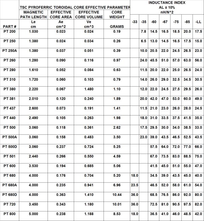
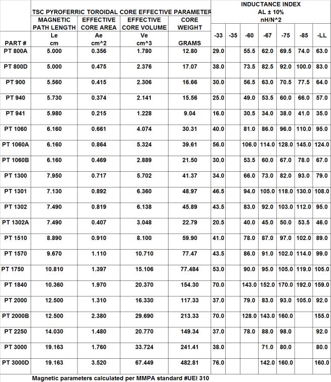
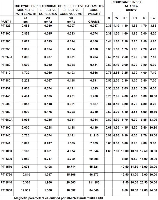
INDUCTANCE FACTOR
The permeability for each material is for reference only. The cores are manufactured to a specific AL value. The AL values are expressed in nanoheneries per turn squared (nH/ N2). To calculate the required number of turns for a specified inductance (L), use the following formula:
required number of turns = [L (nH)/ AL (nH/ N2)]0.5
For the cores listed in the catalog, the AL values are based on measurements at a frequency of 10 KHz and peak AC flux density of 10 gauss (1 millitesla). The E-cores are tested with a 100 turn coil. The toroidal cores are tested with a full single-layer winding. This produces a uniform current sheet and minimizes leakage effects.
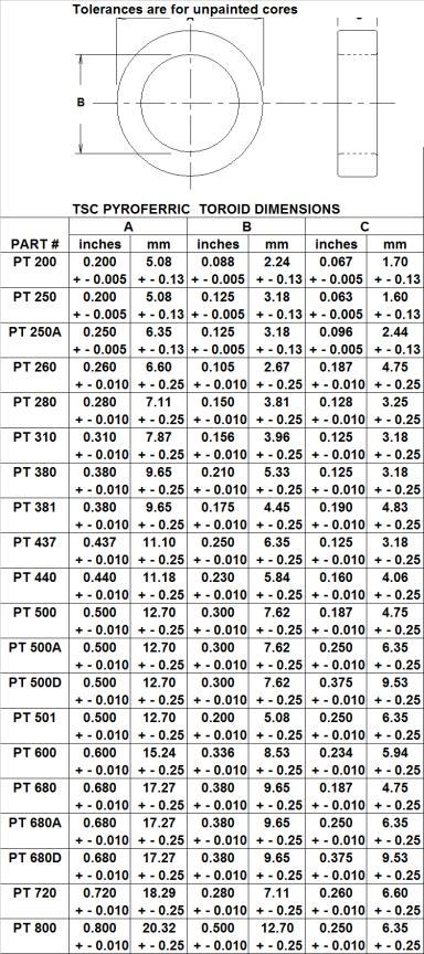
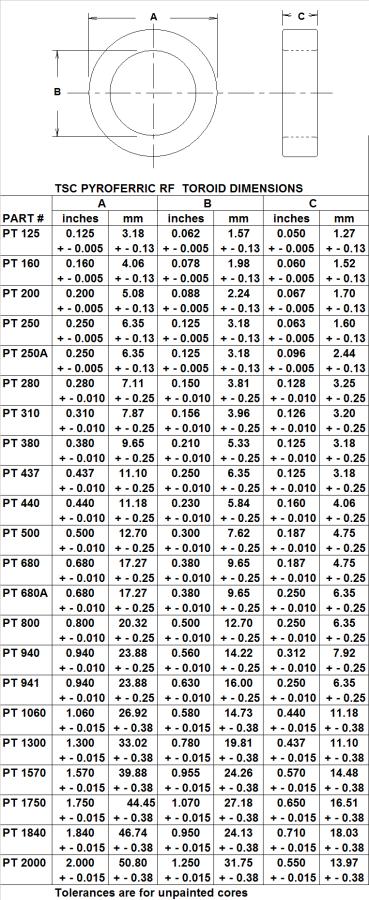
FINISH
Toroidal core sizes PT 200 and PT 250 listed in this catalog are coated with Parylene C. The minimum dielectric strength is 250 volts.
Toroidal core sizes PT 250A and larger are coated with a polyurethane enamel. The cores are color-coded in accordance to material. The minimum dielectric strength is 500 volts. The typical dry film thickness is 4-7 mil, 10 mil maximum.
The E-cores are chemically treated to resist corrosion.
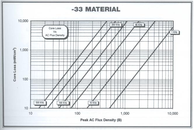
Iron Powder Magnetic Properties
Iron Powder Magnetic Properties
Iron Powder Magnetic Properties
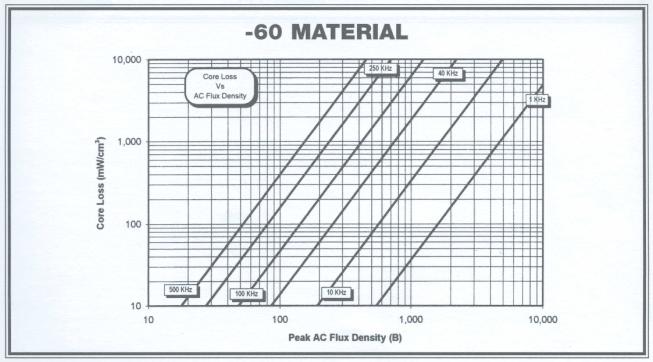
Iron Powder Magnetic Properties
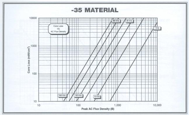 |
Iron Powder Magnetic Properties
 |
 |
 |
 |
RF Applications
RF MATERIAL CHART
|
|
|
Toroidal Color |
Recommended |
|
Core Material |
Permeability |
Code |
Frequency Range |
|
Carbonyl W |
6 |
Gray |
40 MHz-250 MHz |
|
Carbonyl J |
7 |
Gray |
35 MHz-135 MHz |
|
Carbonyl SF |
8 |
Yellow/ Gray |
10 MHz-100 MHz |
|
Carbonyl TH |
8.5 |
Gray |
1 MHz-60 MHz |
|
Carbonyl E |
10 |
Red/ Gray |
100 KHz-25 MHz |
|
Carbonyl C |
20 |
Gray |
50 KHz-5 MHz |
|
Carbonyl GQ4 * |
35 |
White/ Green |
50 KHz-2 MHz |
* For Carbonyl GQ4 (-35) toroidal cores please refer to the Power Conversion Applications section.
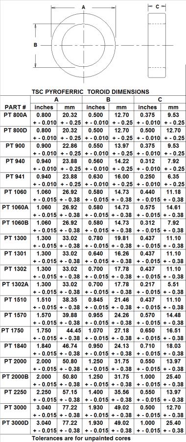
FINISH
Toroidal core sizes PT 125 and PT 250A listed in this catalog are coated with Parylene C. The minimum dielectric strength is 250 volts.
Toroidal core sizes PT 280 and larger are coated with a polyurethane enamel. The cores are color-coded in accordance to material. The minimum dielectric strength is 500 volts. The typical dry film thickness is 4-7 mil, 10 mil maximum.
Q & m COMPARISON CHART
|
Core Material |
Comments |
|
Carbonyl W |
Highest “Q” at recommended frequency range. |
|
Carbonyl J |
Higher “Q” than SF at recommended frequency range. |
|
Carbonyl SF |
Higher “Q” than TH at higher frequencies. |
|
Carbonyl TH |
Higher “Q” than E at higher frequencies. |
|
Carbonyl E |
High “Q”, medium m, high resistance, most common RF material. |
|
Carbonyl C |
Medium m with high “Q”. |
|
Carbonyl GQ4 |
Medium m with high “Q” for special applications. |
 |
 |
 |
GENERAL DATA ON LAMINATIONS
For standard type laminations, the following pages contain information on the types of materials available, their mechanical and physical characteristics, and their electrical and magnetic properties.
TSC-Arnold Technologies’ laminations are made from various grades of electrical steels, silicon steels, nickel-iron alloys, and cold rolled motor lamination steel.
Laminations made from various grades of electrical silicon steels are the most economical for use in small transformers and reactors. These steels are classified according to ASTM A664.
TSC-Arnold Technologies provides grain-oriented laminations in thickness of .006 and .014 (29 gauge) inches. This material shows very low core losses and high permeability in the rolling direction. Laminations made from this material are supplied in a fully stress relief annealed condition with high interlaminar resistance and a high stacking factor.
TSC-Arnold Technologies provides various grades of non-oriented silicon steels. The most common thicknesses are .0185 (26 gauge) and .025 (24 gauge) inches. Silicon content for these types of steels influences the core loss characteristics. Steels with higher silicon contents typically have lower core losses. Laminations made from these grades of steels are supplied in a fully stress relief annealed condition with high interlaminar resistance and high stacking factors.
TSC-Arnold Technologies provides cold rolled motor lamination steel in thickness of .018 (26 gauge) and .025 (24 gauge). Laminations produced from cold rolled motor lamination steel are used in fractional motors and transformers where low core losses are not critical and better permeability at a high KG is desired. Laminations made from this material are supplied in a fully stress relief annealed condition.
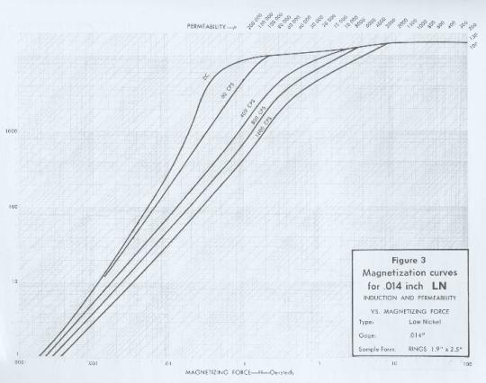
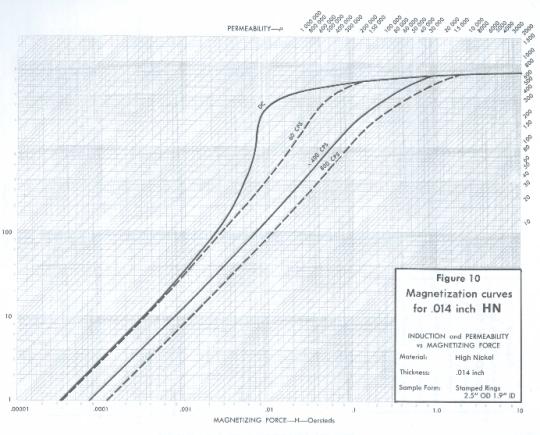
Laminations produced from both low nickel iron alloys (50% nickel) and high nickel iron alloys (80% nickel) are used where both high performance and compactness are essential.
High Nickel-Iron Alloys (80% Nickel)
TSC-Arnold Technologies provides high nickel alloys in
thickness of .006” and .014”
(29 gauge). This material has very
high initial and maximum permeability for use in low density, high frequency
applications, including telecommunications, ground fault interrupters and
magnetic shielding. Laminations made
from this material are supplied in a fully annealed condition, for highest permeability
or lowest total harmonic distortion, with an inorganic coating for an optimum
stacking factor. The thickness and the
designation HN is used as a suffix after the lamination shape to form the
catalog part number. For example: EI375-0140-HN.
Low Nickel-Iron Alloys (50% Nickel)
TSC-Arnold Technologies provides low nickel alloys in
thickness of .006” and .014”
(29 gauge). This material shows high initial and maximum permeability for use
in moderately low flux density applications, such as: servomotors, relay, armatures, and solenoids. Laminations made from this material are
supplied in a fully annealed condition, assuring high permeability, with an
inorganic coating for an optimum stacking factor. The thickness and the
designation LN is used as a suffix after the lamination shape to form the
catalog part number. For example: EI375-0140-LN.
MECHANICAL AND PHYSICAL CHARACTERISTICS
TSC-Arnold Technologies’ lamination standards for all applicable mechanical and physical characteristics meet or exceed the recognized industry standards. The most important of these are:
By maintaining the below listed tolerances, TSC-Arnold Technologies’ laminations have a mechanical consistency that ensures good stacking characteristics and low gap losses.
|
Gauge No. |
Gauge Thickness |
Gauge Tolerance + or - |
Burr Tolerance Max |
Dimension Tolerances + or - |
Flatness* Tolerances |
|
29 |
.0140 |
.001 |
.0020** |
.005 |
.022 |
|
26 |
.0185 |
.002 |
.0025 |
.005 |
.028 |
|
24 |
.0250 |
.003 |
.0030 |
.005 |
.035 |
|
* 1½” center leg and under measured with a bridge type gauge |
|
||||
|
** Nickel is .0010 |
|
|
|||
The normal surface oxide on both silicon and nickel flat rolled steels provides some degree of interlamination resistance, which may be adequate for many applications. However, as additional interlamination resistance is generally desired, TSC-Arnold Technologies’ laminations are coated with one of the following inorganic coatings:
|
Material |
Coating Type |
AISI Type |
|
Grain Oriented |
C-10 |
C-4 |
|
Non-Oriented |
C-5 |
C-5 |
|
Nickel (High & Low) |
Magnesium Oxide or |
- - |
|
|
Magnesium Methylate (Type 2) |
|
Various methods of packaging, depending on the part number, are used for the maximum protection of the laminations in transit. Regardless of the method employed, all have the following standards:
v
E and I laminations
must be packed together as stamped to insure
equal thickness and quantities.
v
The thickness
variation between E and I laminations in any one
carton cannot exceed ± 2%.
v
A layer of rust
inhibiting paper (V.C.I. or equivalent) shall be packed
between lamination layers.
 |
 |
 |
 |
CORE SIZE SELECTION FOR POWER TRANSFORMERS
A Power Transformers Core selection is dependent on the amount of power the core will need to handle. A relationship between apparent Power (Pt) and Area Product (WaAe) can be derived from Faraday’s Law as follows:
Faraday’s Law Np
= ![]() Ns
=
Ns
= ![]()
Winding Area UtilizationKuWa
= Np Awp +
NsAws (by definition Aw = ![]() )
)
Substituting ![]() for Aw KuWa = Np
for Aw KuWa = Np ![]() + Ns
+ Ns ![]()
Substituting ![]() for Np and Ns
for Np and Ns
KuWa = 
![]() +
+ 
![]()
Rearranging WaAe = ![]()
Input Power Pin = VP Ip = ![]()
Output Power = Po = VsIs
Apparent Power = Pt =
Pin +
Po = ![]()
Substituting Ap =
WaAe = ![]()
J = Current density (A/cm2)
Ke = Wave Form Coefficient (typically 4 for square wave)
Ku = Window Utilization Factor (typically 0.4)
Wa = Window Area (winding area cm2)
Np = Primary Turns
Ns = Secondary Turns
Ip = Primary Current in amperes
Is = Secondary Current in amperes
Vp = Primary Voltage
Vs = Secondary Voltage
Pt = Apparent Power (watts)
Po = Output Power (watts)
Pin = Input Power (watts)
h = Efficiency
Ae = Effective core cross sectional area in cm2
B = Maximum Operating Flux density in tesla
f = Frequency in Hz
WaAe is published for each of our cores in cm4
REFERENCES
Annual book for ASTM Standards Volume 03.04
Metals Test Methods and Analytical Procedures for Magnetic Properties…
Available from: American Society for Testing and Materials
100 Barr Harbor Drive
West Conshohocken, PA 194288-2959
Phone: (610) 832-9500
IMA Publications on Soft Ferrites
Soft Ferrites A User's Guide
Standard No. UEI 310 Standard Specifications for Ferrite U,E&I cores
Standard No. PC 110 Standard Specifications for Ferrite Pot Cores
Standard No. FTC 410 Standard Specifications for Ferrite Toroid Cores
Permanent Magnet Guidelines
Standard No. 0100-90 Standard Specifications for Permanent Magnet Materials
Available from: International Magnetics Association
8 South Michigan Avenue, Suite 1000
Chicago, IL 60603
Phone: (312) 456-5590
FAX: (312) 580-0165
Metric System SI Units
|
Quantity |
Metric Symbol |
Metric SI Units |
Customary Symbol |
Customary Units |
Multiplication Factor to Convert from Customary Units to SI Units |
|
Area |
m2 |
Square meter |
cm2 |
Square centimeter |
1x10⁻⁴ |
|
Celsius Temperature |
OC |
Degree Celsius |
OF |
Degree Fahrenheit |
(F-32)*5/9 |
|
Density |
kg/m3 |
Kilogram per cubic meter |
g/cm3 |
Gram per cubic centimeter |
1x10³ |
|
Electric resistance |
W |
Ohm |
W |
Ohm |
1 |
|
Electrical charge |
C |
Coulomb |
E.M. |
Electric charge per mass |
10 |
|
Electric current |
A |
Ampere |
I |
Ampere |
1 |
|
Electrical potential, electromotive force |
V |
Volt |
E |
Volt |
1 |
|
Energy, work |
J |
Joule |
ERG |
Centimeter-gram-second |
1x10⁻⁷ |
|
Force |
N |
Newton |
# |
Pounds |
4.44822 |
|
Frequency |
Hz |
Hertz |
kHz |
Kilohertz |
1x10³ |
|
Inductance, Inductor |
H |
Henry |
L |
Henry |
1 |
|
Length |
m |
Meter |
cm |
Centimeter |
1x10⁻² |
|
Magnetic field strength |
A/m |
Ampere per meter |
Oe |
Oersteds |
79.58 |
|
Magnetic flux |
Wb |
Weber |
Mx |
Maxwell |
1x10⁻⁸ |
|
Magnetic flux density, Magnetic Induction |
T |
Tesla |
g |
Gausses |
1x10⁻⁴ |
|
Mass |
kg |
Kilogram |
g |
Gram |
1x10⁻³ |
|
Permeability |
H/m |
Henry per meter |
m |
(Unit less) |
4x10⁻⁷ |
|
Power |
W |
Watt |
W |
Mw |
1x10⁻³ |
|
Power Loss Density |
kW/m3 |
Kilowatt per cubic meter |
Pc |
mW/cm3 |
1 |
|
Pressure, stress |
Pa |
Pascal
|
PSI |
Lbs/in2
|
6896.5 |
|
Thermal conductivity |
W/(m*K) |
Watt per meter Kelvin |
|
|
|
|
Time |
S |
Second |
S |
Second |
1 |
|
Volume |
m3 |
Cubic meter |
cm3 |
Cubic centimeter |
1x10⁻⁶ |
 |
FORMULAS FOR CALCULATING QUALITY METRICS |
|||
|
VARIABLE DATA |
|||
|
|
|
|
|
|
METRIC |
Double Sided |
Single
Sided with |
Single
Sided with |
|
|
|
|
|
|
Cp |
(USL-LSL)/6s |
(USL-m)/3s |
(m-LSL)/3s |
|
|
|
|
|
|
K |
|T-m|/(USL-LSL)(0.5) |
|T-M|/(T-USL) |
|T-m|/(LSL-T) |
|
|
|
|
|
|
Cpk |
Cp(1-k) |
Cp(1-k) |
Cp(1-k) |
|
|
|
|
|
|
Sigma |
3 Cpk |
3Cpk |
3Cpk |
|
|
|
|
|
|
|
|
|
|
|
Where: |
|
|
|
|
|
Cp = Centered process capability |
|
|
|
|
k = Process mean offset |
|
|
|
|
Cpk = Process capability |
|
|
|
|
m = sample mean |
|
|
|
|
s = sample standard deviation |
|
|
|
|
USL = Upper spec limit |
|
|
|
|
LSL = Lower spec limit |
|
|
|
|
T = Target value |
|
|
TSC INTERNATIONAL
WARRANTIES AND DISCLAIMERS
“TSC International” expressly warrants to the “Buyer” for whom it manufactures, sells and delivers product made of magnetic materials will conform to specifications and drawings as published within the product catalog. Buyer specifications that have not been approved by the International Electronic Commission shall be considered as a custom product, and will be warranted by TSC International for the buyer in a separate written agreement.
There are no other express or implied warranties which extend beyond the above-referenced warranty of conformity to the specifications and specifically, TSC International does not warrant that any product will be merchantable or fit for the particular purpose for which the purchaser, it successors, agents, assigns or affiliates, intends to use such product.
Buyer shall notify TSC International in writing (and reasonable detail) of any defect in any product within thirty (30) days after the delivery date thereof. If products do not conform to the specification, buyer’s remedy shall be limited, at TSC International’s sole discretion, to either (1) The return of such product in exchange for the return of or credit for any payment received by TSC International relating thereto; (2) The replacement of such product; or (3) The repair of such product. TSC International shall pay for all reasonable shipping costs incurred in connection with the return, replacement or repair of any defective product. Solution to resolve defective product shall be within (60) days after receipt of written notice from buyer of such defect.
TSC International shall not be liable for any incidental or consequential loss, damage or expense (including without limitation, economic loss or lost profits) or buyer for any defective product sold and delivered to buyer regardless or whether such loss, damage or expense results from a breach of contract or warranty or commission of a tort (including, without limitation, strict liability or negligence).
 |
ISSUE DATE: 2007
|
|
|
|
|
|
|